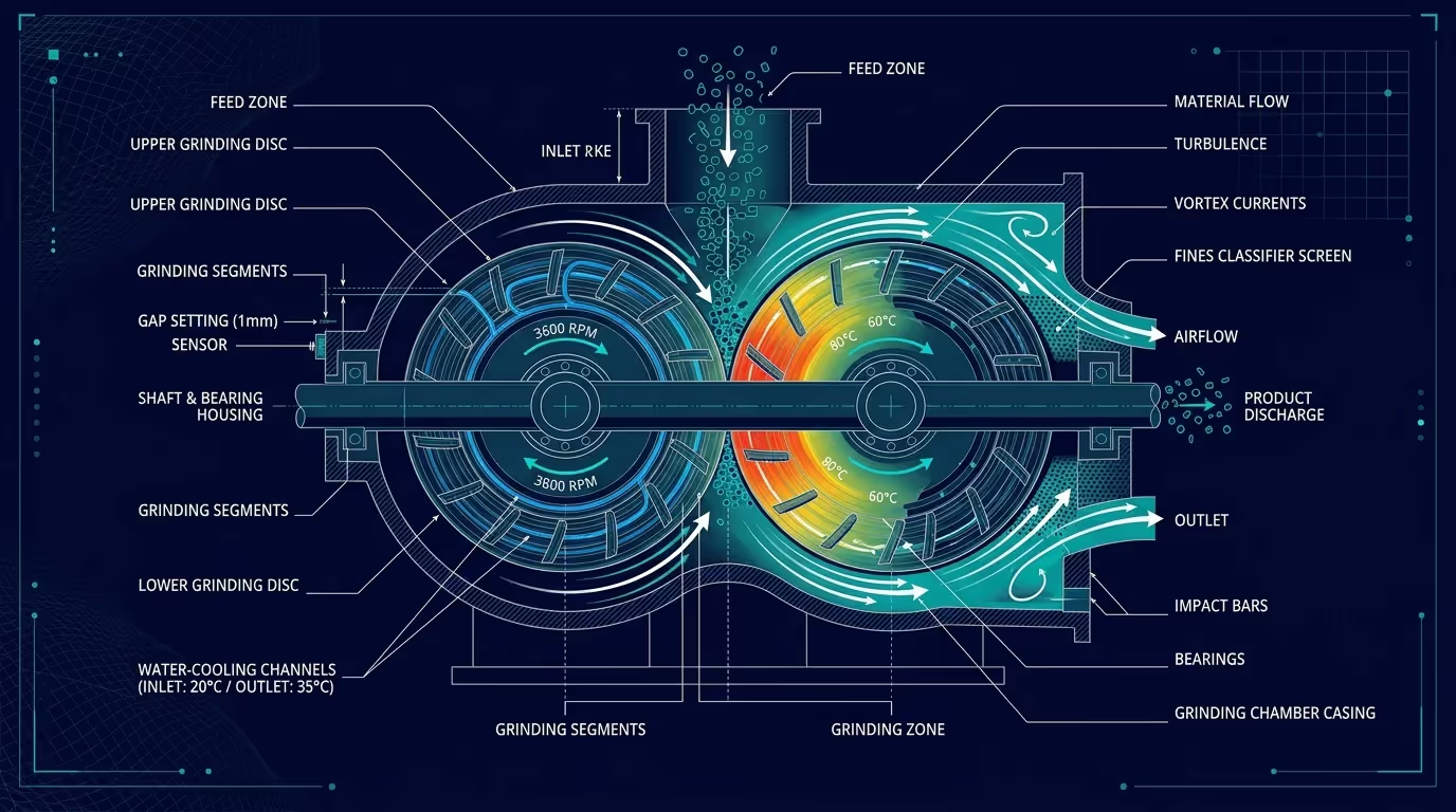
In rigid PVC pipe, profile, and foam-board recycling lines, the plastic pulverizer is subjected to severe mechanical and thermal stresses. Unlike softer polyolefins, unplasticized PVC (PVC-U) is notoriously heat-sensitive: if the milling temperature exceeds approximately 65°C to 70°C, the material reaches its glass transition temperature and softens.
At this point, instead of shattering under shear, PVC begins to smear across the disc teeth, glazing the grinding surfaces, triggering thermal degradation (burning and release of corrosive HCl gas), and causing immediate machine stoppage.
Proper thermal regulation and systematic wear-part maintenance are the difference between an efficient 800 kg/h grinding operation and recurring, costly downtime. In this technical guide, we break down proven maintenance routines to prevent overheating, extend disc life, and keep powder output within tight mesh specifications.
For detailed equipment specifications, explore the plastic pulverizer machine platform.
The Primary Causes of Pulverizer Overheating
Excessive temperature inside the grinding chamber can almost always be traced to four mechanical and operational factors:
1. Dull or Glazed Grinding Disc Teeth
As the sharp cutting edges of the rotating and stationary discs wear down, the mechanism shifts from clean shear to abrasive friction. Friction generates intense thermal spikes without increasing powder throughput. Operators often attempt to compensate for dull blades by tightening the disc gap, which compounds the frictional heat and accelerates motor overload.
2. Scaled or Air-Locked Cooling Water Jackets
Industrial pulverizers rely on high-flow water cooling jackets surrounding the mill door and stationary disc housing. Over months of continuous operation:
- Hard mineral deposits (scale) coat the internal water channels, acting as a thermal insulator.
- Air pockets in the cooling loop reduce effective heat transfer by up to 40%.
- A cooling water inlet temperature exceeding 25°C significantly limits the system’s heat extraction delta.
3. Starved Airflow in Negative-Pressure Conveying
The forced suction airflow generated by the induced-draft fan does more than transport finished powder to the cyclone separator—it acts as an essential convective cooling medium. Clogged dust collector filter bags or partially blocked ductwork restrict chamber airflow, trapping hot air inside the housing.
4. Excessive or Surging Infeed Rate
Sudden surges in feedstock volume overfill the grinding chamber, forcing the discs to mill material faster than heat can be dissipated.
4-Step Engineering Protocol to Eliminate Chamber Overheating
[1. Precision Gap Calibration] -> [2. Water Jacket Flushing] -> [3. Airflow Balancing] -> [4. Sensor Integration]Step 1: Calibrate Disc Gap Using Feeler Gauges
Maintaining a uniform clearance between the stationary and rotary discs ensures maximum shear efficiency with minimal heat buildup:
- Always check clearance at four opposite quadrant points (0°, 90°, 180°, 270°) around the perimeter.
- Target gap for PVC regrind (30–60 mesh): 0.30mm to 0.45mm depending on required fineness.
- Never adjust discs while the chamber is hot. Thermal expansion will cause inaccurate readings; always calibrate when the machine has cooled to ambient room temperature.
Step 2: Implement a Closed-Loop Chiller Circuit
Relying on open cooling towers often introduces algae and mineral scale into narrow jacket channels.
- Use an industrial water chiller maintaining cooling water inlet temperature between 12°C and 18°C.
- Ensure water flow rate meets manufacturer specs (minimum 2.5–4.0 m³/h per grinding head).
- Perform a quarterly descaling flush using a mild acidic cleaning solution to remove mineral deposits and preserve maximum thermal transfer.
Step 3: Monitor Differential Pressure on Dust Bags
Inspect your negative-pressure pulse-jet baghouse daily. When the pressure differential across the filter bags exceeds 1,200 Pa, the airflow through the pulverizer chamber drops sharply. Replace glazed filter bags and ensure the pulse cleaning cycle is operating at correct compressed air pressure (0.5–0.6 MPa).
Step 4: Automate Feeder Regulation via Motor Amperage (VFD Interlock)
The most effective way to eliminate human error is an automated feed control loop:
- The infeed vibratory or screw feeder motor should be linked to the main pulverizer motor amperage via PLC.
- If chamber temperature climbs above 65°C or main drive current exceeds 90% of full-load amps, the feeder automatically slows down, allowing the cooling systems to restore normal operating parameters before jamming occurs.
Disc Inspection and Resharpening Schedule
| Operating Hours | Inspection Item | Recommended Action |
|---|---|---|
| Every 8 Hours (Shift End) | Chamber visual inspection | Check for PVC buildup or discolored resin indicating hot spots |
| Every 50 Hours | Feeler gauge gap check | Verify four-point gap consistency; adjust if deviation > 0.05mm |
| Every 300–500 Hours | Tooth profile wear measurement | Inspect leading edge radius. If radius > 1.0mm, rotate or invert segment |
| Every 800–1,200 Hours | Precision surface regrinding | Send disc segments to specialized grinding shop for tooth re-profiling |
Summary
Controlling thermal buildup in your PVC pulverizer protects your raw material quality, avoids hazardous chemical degradation, and dramatically lowers your kilowatt-hour cost per ton of produced powder.
By maintaining sharp grinding segments, descaling cooling jackets, and ensuring adequate pneumatic airflow, your pulverizer can reliably operate around the clock with zero unscheduled stops.
Ready to optimize your plastic pulverizing operations? Visit the Repolyx Plastic Pulverizer page for technical consultation and spare wear parts.